Singapore Robotic Games 1998
NATIONAL UNIVERSITY OF SINGAPORE
COMPETITION HALL, SRC
19 - 22 MAY 1998
Any mechanism which supports an inverted pendulum which is free to swing around a horizontal axis with one degree of freedom and balances it to keep it vertical by moving the point of support shall be considered "the pole balancing robot."
2.1 The inverted pendulum may be supported by a vehicle moving along a straight line. Any other innovative design, which does not violate the spirit of the competition, may be allowed at the discretion of the judges subject to the following conditions:
2.2 The inverted pendulum must be free to swing. It must be balanced by moving the pivoted support point parallel to the plane of the swing. The pivot must be fixed to the vehicle.
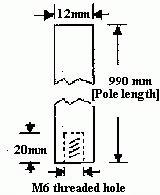
2.3 The robot must use a standard contest balance pole specified by the organisers. A sample pole will be supplied for the institutions participating in the competition. The pole material will be aluminium.
2.4 There is no size restriction on the robot. No part of the robot, other than the its wheels, must touch the surface of balance table. It must not fall off the competition table surface during the operation. No part of the robot can protrude outside of the balance table at the start of the competition.
2.5 Balancing the pendulum/pole using any form of gyroscopic principle is not admissible.
2.6 A self-balancing design in which the pendulum will always stand up due to the use of a balance weight below the axis of rotation is also not admissible.
2.7 There should be no relative motion between the pole-support axis and the body of the vehicle.
2.8 No guide rails are allowed.
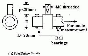
3.1 The supporting mechanism must be compatible to the diagram shown in Fig. 1. Ball bearings must be used in the axle of rotation supporting the pole, only exception being the instrumentation potentiometer or encoder. If the potentiometer or encoder is driven through gears then the gear friction must be very small as quantified in section 3.2. It must be able to swing freely from -45° to +45° from the vertical position when the vehicle is positioned in region B.
3.2 The friction of the suspension mechanism is quantified as follows:
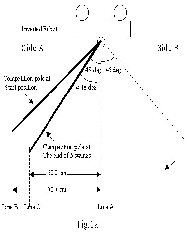
The pole used for balancing is also used for this purpose. The robot will be placed upside-down to make the pole a regular pendulum, as shown in Fig.1a.
For the test, the robot is supported upside down such that the axle is on the vertical line A, marked on the wall or the platform built for this purpose. There will be two vertical lines on the left side. One will (extreme left line B) correspond to 45° inclination of the pole. The second inner line C will correspond to 30.0 cm from the equilibrium point, which is about 18° inclination of the pole.
The pole is moved to side A to reach an inclination of 45° such that the tip touches the outer vertical line and is released, so that it swings back and forth. At the end of the fifth swing cycle the pole should swing back to side A and reach a minimum angle of 18° such that the tip touches the inner vertical line C.
3.3 The overall size will be such that it would be able to operate on the table provided by the organisers.
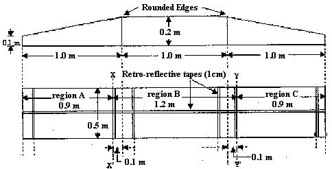
4.1 The competition table is shown in Fig.2. One common competition table will be used by all competitors. The gradient will be approximately 5.7 degrees. The edges between the inclined surfaces and the horizontal surface will be rounded off and there will be no joints at those edges. A neoprene rubber mat of 3-mm thickness will be used on the top of the table to improve the grip of the wheels.
5.1 The intelligence for the robot can come from a PC, which may communicates by wireless means to the electronics controlling the drive mechanism. In such cases, the program in the executable file form shall be in control of the robot throughout the duration of the robot's performance without human intervention except for re-starting the execution of the same program.
5.2 The vehicle must be physically autonomous, with no wires connected externally, in which case no switching of EPROM's or switching of programs using human intervention will be allowed.
5.3 No external power supply is allowed.
6.1 The robotic vehicle would operate on the top of the table provided. Please see Fig. 2. The tabletop will have a slight gradient at the start (region A) and the end (region B) zones as shown in Fig. 2.
6.2 The vehicle will be placed within the region A (see Fig. 2). The operator may move the pole (the inverted pendulum) to an upright position and release it upon receiving the signal from the judges. The vehicle must balance the pole in the upright position for a minimum of 20 seconds without the vertical pole crossing the line X-X'.
6.3 Upon completion of the task (in 6.2 above), the vehicle should move across the line X-X' once, and move through the region B, until the pole clears the line Y-Y', without losing balance during transit, i.e. not hitting any part of the table or its own chassis.
6.4 The performance of a vehicle, which moves while the pole is falling off to horizontal position, will not be admissible.
6.5 Upon completion of task (in 6.3 above), the vehicle must retrace the path, cross the line X-X' again and get back to region A. This will complete one cycle. This time, during the retrace, the vehicle need not stay any length of time at region B or A, before the start of the second cycle.
6.6 The vehicle should repeat these cycles.
6.7 To count these cycles as successful cycles they must be followed by at least 20 seconds of static balancing at region A.
6.8 The robot may continue on (untouched) for more cycles, which if successful will be counted cumulatively.
6.9 If the robot is touched by the handler during the trial, it must be restarted for the next attempt.
7.1 The vehicle with the highest number of successful cycles in a single untouched attempt will be considered the winning entry. Subsequent places will be decided similarly.
7.2 If necessary, the number of successful cycles in further attempts will be used as a tie-breaker.
7.3 If the tie is not broken by 7.2, the number of unsuccessful cycles will be considered.
7.4 If there is still a tie, it will be left to the discretion of the judges.
8.1 5 minutes will be allowed for each robot. Within the time permitted, any number of attempts will be allowed.
8.2 The time will start one minute after the name of the participant is called, or when the robot is first released by the participant, whichever is sooner.
8.3 The participants must vacate the competition area after the 5 minutes expire.
9.1 In accordance with the spirit of the competition, clones among the winning entries will only be awarded one prize. Clones will be identified during the "caging" procedure.
9.2 Clones are robots with substantially identical physical appearance and working principles.
9.3 When in doubt, the decision of the Judges will be final.